Universal counterweight cover

Construction according to EN 81-20 5.2.5.5.1


Counterweight cover

Description

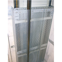
Due to the adjustable angles and brackets as well as the corresponding perforated sheets the counterweight cover virtually fits in every concrete lift shaft.
According to EN 81 -20, the cover shall extend from the lowest point of the counterweight resting on the fully compressed buffer or the lowest position of the counterweight to a height of at least 2.0 m above the bottom of the shaft pit.
The distance between the bottom of the shaft pit and the lowest part of the separation must not exceed 0.30 m in any case.
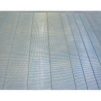
High form stability due to three surrounding brackets and 1.5mm thick galvanised perforated sheet panels. The depth and the width of the fastening angles and brackets are universally adjustable.

Mounting and transport

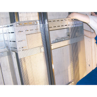
Instructions for mounting


To mount this cover a water level, a drilling machine and a portable ladder are required. In some cases a cut-off grinder is needed additionally.
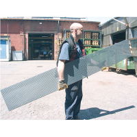
The delivery is effected in manageable packages. Transport to the building site is possible with a regular estate car.

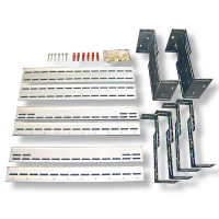
Scope of delivery standard package

Accessories

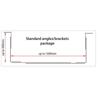
Standard package: Angle, clamp, screw, dowel set and panels for
a width up to 1600mm and a depth up to 450mm including:
4 pieces of panels 2.0m x 0.31m and 4 pieces of panels 2.0m x 0.15m

Single panels with:
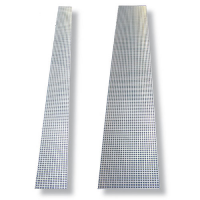
2.0m x 0.15m and 2.0m x 0.31m

Products

Description
Counter weight cover-VK-SP (078550)
Counter weight cover standard package. Includes complete clamps package, 4 pcs. panels 2.0m x 0.31m and 4 pcs. panels 2.0m x 0.15m and all fastening parts.
Single panel 150 (078552)
Additional single panel, galvanised perforated sheet with holes of 8x8mm, 2.0m x 0.15m.
Single panel 310 (078551)
Additional single panel, galvanised perforated sheet with holes of 8x8mm, 2.0m x 0.31m.
Counter weight cover-VK-WB (078553)
Single angle and bracket package, including screw and dowel set, without panels.