W+W Travel path limitation

for the protection of the safety space in the shaft head


Travel path limitation

Intended use

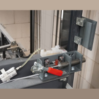
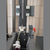
Mounting examples

The W+W Travel path limitation has been type-tested by TÜV Rheinland.
You will find the download at the bottom of the page.

If the shaft head is reduced in cable lift installations, there is not enough protective space for maintenance and inspection staff when the car reaches its mechanically highest possible position (counterweight is on the buffer).
Therefore, equivalent substitute measures must be created to guarantee this protective space in order to prevent personal injury even in case of malfunction.
If a general malfunction leads to a movement exceeding the travel path of the defined inspection travel, a mechanical protection limiting the travel path is required, which can be provided e.g. by a maintenance support under the counterweight. As this solution is not very practical, it is recommended to install the protection at the required position on the car roof.

Installation conditions

Functional description

The specified nominal load ranges are valid for:
- counterweight compensation 50%
- max. release speed from 2.1m/s
1000 - 1600kg:
- car empty weight F from 0.8 to 1.4 x nominal load Q (but Fmax= 1900kg)
400 - 600kg / 600 - 1000kg:
- car empty weight F from 1.0 to 1.4 x nominal load Q

In general:
The device is mounted on the left and right directly on or under the head beam of the support frame. The angle with the bolt must make full contact with the support frame. A mounting on the cabin is not permissible.

After a case of damage has occurred and the protective
space system has been used, it must be completely replaced!


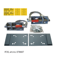
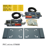
Travel path limitation art.no. 078687 and art.no. 078688

In case of a reduced shaft head it is necessary to create the protective space required by the standard with suitable substitute measures and to limit the inspection travel upwards. This is achieved at first by a limit switch for the inspection travel or another electronic switch-off (e.g. ELGO Limax 33CP Safe, Kübler PSU02 *). If, in the rare event of a malfunction, the electronic switch-off does not stop the inspection travel, a mechanical protection must end this journey so that no personal injury can occur under any circumstances.
* SIL3- systems are comparably safe as limit switches.

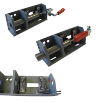
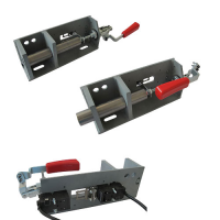
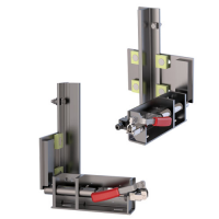
The W+W travel path limitation is the mechanical part of this protective space protection in the shaft head. The device consists of two holders, which are mounted on the car roof at the supporting frame, each with a bolt which can be manually extended and retracted. Additionally, a limit stop plate is mounted on each of the rails.

In lift systems according to EN 81-20 or in the presence of a UCM system, the moment when the user enters the car roof (static situation) can be considered sufficiently safe. The bolts must then be extended manually. Only when both bolts are fully extended is the inspection travel released via the safety contacts.
If the inspection travel is not stopped electrically in the case of a malfunction, the bolts hit the limit stop plates which end the upward movement. The stop plates are positioned in a way that the distances in the shaft head correspond at least to the requirements of EN 81-20 point 5.2.5.7.
Before leaving the car roof, both bolts must be fully retracted again. Only in this state a reset and thus a return to normal operation is possible.

.

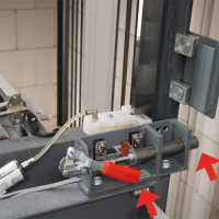
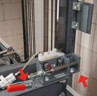
Mounting examples travel path limitation

Requirement according to EN 81-20

Travel path limitation extended and retracted

As this is not an automatic system, precautions must be made to prevent car movement before stepping onto the car roof and activating the inspection travel release device. Entering the car must be reliably detected and all travel functions must be deactivated by this detection. In new installations, this is usually done by monitoring the emergency release. For retrofitting, for example, a contact mat or a light grid on the car can also be used for detection. Inspection operation must then be possible only when the protective space system is activated and normal operation must be possible only after a reset.

The pre-release stop system required by EN 81-21 point 5.5.2.2 can be the same system used for the UCM system. The system may only be reset to normal operation by actuating an electrical reset device conforming to EN 81-21. Since this variant is a deviation from EN 81-20, a hazard analysis with the contents specified above has to be made.

Mounting limit stop plates

Important mounting advice!

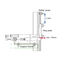
The stop plates are attached to the guide rails by means of clamping plates. When the bolts hit the stop plates, the clamping plates slide up on the rail, which provides a defined deceleration path.
In the most unfavourable case, a locking screw stops the movement completely.

Mounting advice, nominal load 400 - < 600kg and 600 - 1600kg

1. When the bolts hit the stop plates at release speed, high forces are transmitted to the device and consequently also to the support frame. Therefore, these must be mounted in a suitable place. The device is mounted on the left and right directly on or under the head beam of the support frame. The angle with the bolt must make full contact with the support frame. A mounting on the cabin is not permissible.

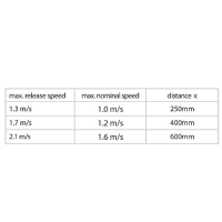
2. The safety screws are positioned so that the distances in the shaft head comply at least with the requirements of EN 81-20 point 5.2.5.7. The stop plates are mounted with the distance x below. The release speed is relevant for the distance! Before mounting, clean the rails (free of grease and oil)!

3. The bolt must hit the stop plate with a length of at least 10mm in the extended state.

Advice on the deceleration:

For 400 - < 600kg the stop plates are attached to the rail via 2 clamping plates each and for 600 - 1600kg via 4 clamping plates each. A controlled slipping of the stop plates is achieved by means of the tightening torques (deceleration <1g).

The distance between the locking screw <-> stop plate is determined by the release speed!

Scope of delivery

Included in delivery

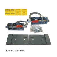
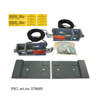
Scope of delivery for art.no. 078684 and 078685

Scope of delivery for art.no. 078687 and 078688

1 x Travel path limitation bolts on the left
1 x Travel path limitation bolts on the right
2 x Limit stop plates
1 x Fixation material (various clamping plates, screws)
1 x Mounting instruction

The technical data for the article can be found under the respective products!

Products

Description
Travel path limitation IP20 400 - < 600kg set T90 (078684)
Travel path limitation IP20 400 - < 600kg set T90. The set contains: 1 x travel path limitation bolts on the left, 1 x travel path limitation bolts on the right, 2 x limit stop plates, 1 x fixation material (various clamping plates, screws), 1 x mounting instruction.
Travel path limitation IP67 400 - < 600kg set T90 (078685)
Travel path limitation IP67 400 - < 600kg set T90. The set contains: 1 x travel path limitation bolts on the left, 1 x travel path limitation bolts on the right, 2 x limit stop plates, 1 x fixation material (various clamping plates, screws), 1 x mounting instruction.
Travel path limitation IP20 400 - < 600kg set T70 (078693)
Travel path limitation IP20 400 - < 600kg set T70. The set contains: 1 x travel path limitation bolts on the left, 1 x travel path limitation bolts on the right, 2 x limit stop plates, 1 x fixation material (various clamping plates, screws), 1 x mounting instruction.
Travel path limitation IP20 400 - < 600kg set T75 (078694)
Travel path limitation IP20 400 - < 600kg set T75. The set contains: 1 x travel path limitation bolts on the left, 1 x travel path limitation bolts on the right, 2 x limit stop plates, 1 x fixation material (various clamping plates, screws), 1 x mounting instruction.
Travel path limitation IP20, 600-1600kg set (078687)
Travel path limitation IP20 600-1600kg. The set contains: 1 x travel path limitation bolts on the left, 1 x travel path limitation bolts on the right, 2 x limit stop plates, 1 x fixation material (various clamping plates, screws), 1 x mounting instruction.
Travel path limitation IP67 600-1600kg set (078688)
Travel path limitation IP67 600-1600kg set. The set contains: 1 x travel path limitation bolts on the left, 1 x travel path limitation bolts on the right, 2 x limit stop plates, 1 x fixation material (various clamping plates, screws), 1 x mounting instruction.